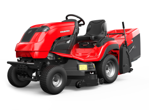
 C Series
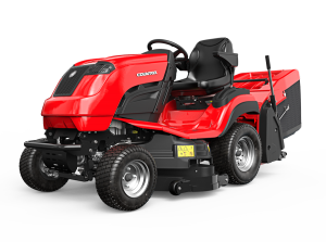 B Series 4WD
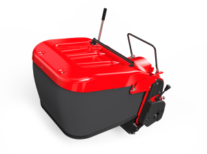 Accessories
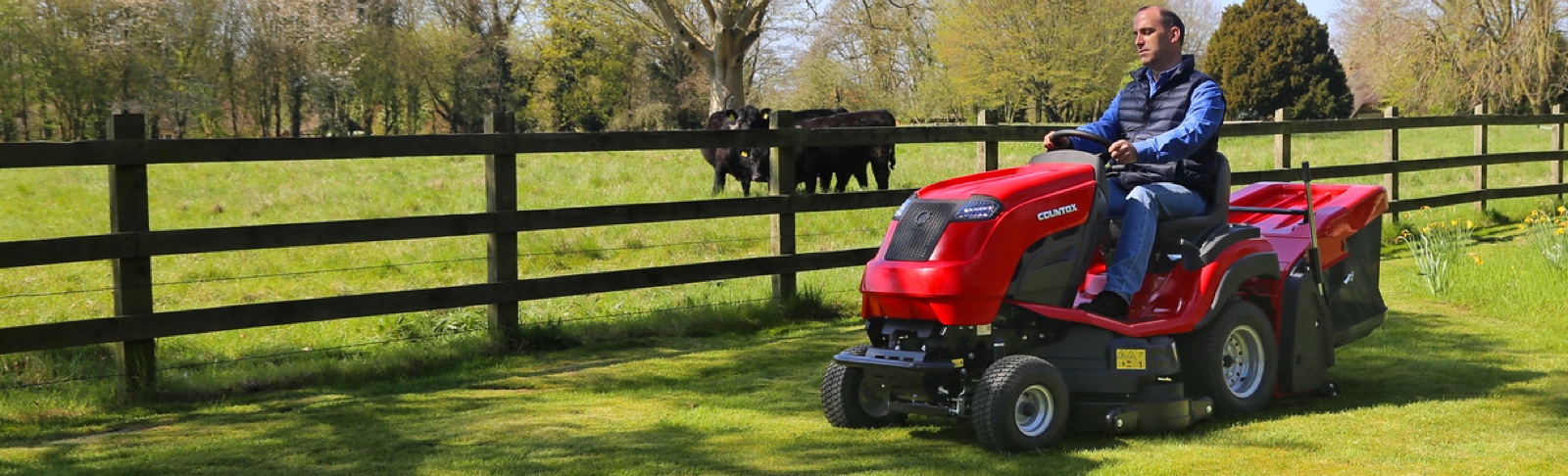
Countax garden tractors are designed, engineered and built in Britain for the British garden. If you have recently purchased a Countax, or are considering one, you may well be interested in the many different stages they have gone through to get to your garden.
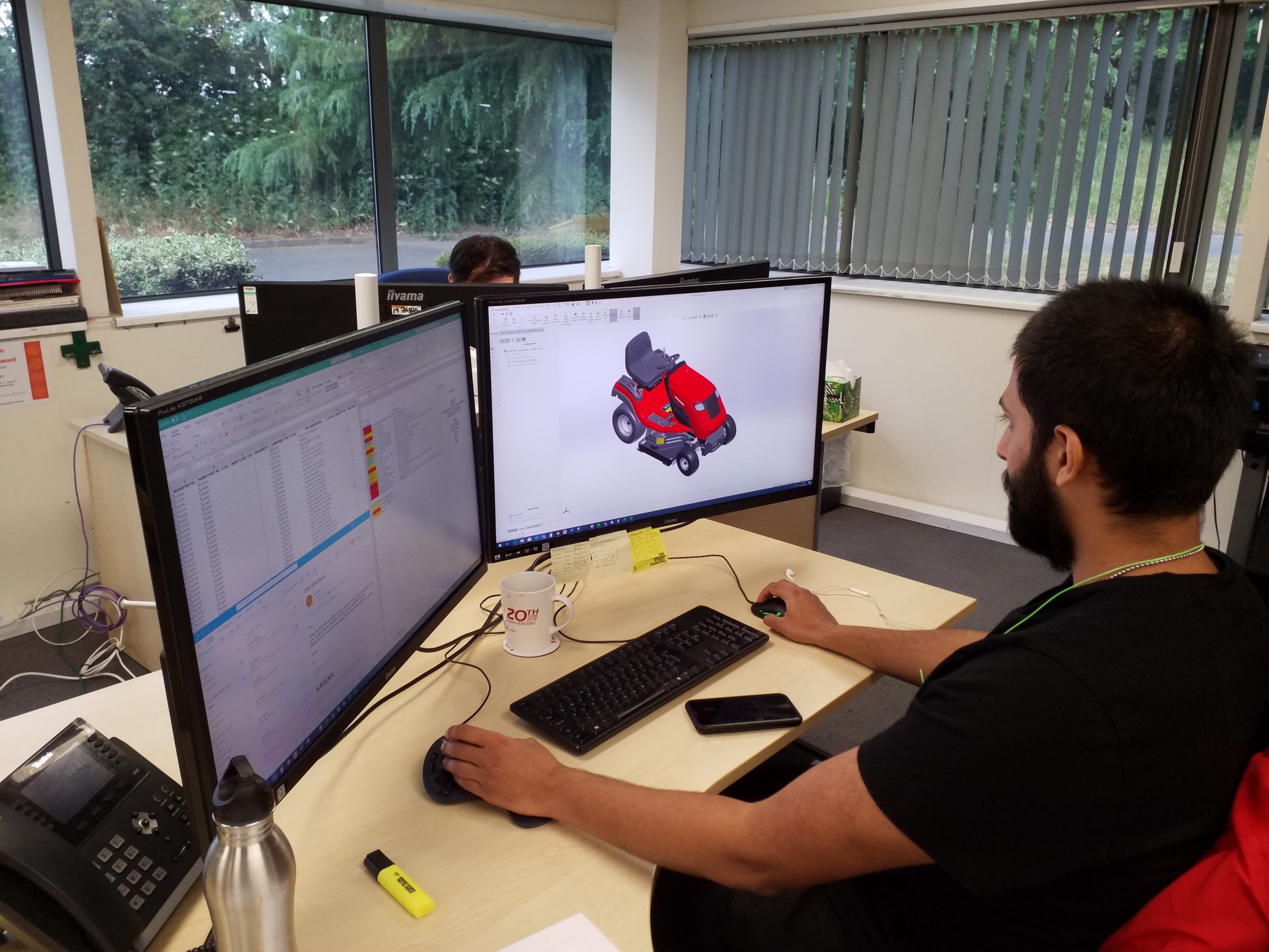
We’ll start by looking at the design office and show you an example of how the design work starts on screen, is then built and tested before it’s approved for manufacture.
What are design engineers?
A design engineer is involved with creating initial concepts, developing designs, and managing projects. Design engineers need strong technical knowledge, as well as problem solving abilities, communication, leadership, and project management skills.
Depending on their specialist area, design engineers may also be known as CAD engineers, mechanical engineers, and industrial design engineers.
What is CAD?
Computer-aided design (CAD) is the use of computers and software to aid in the development, analysis, and optimisation of a component or finished product. CAD is used as a tool to enable the design engineer to develop, analyse and visualise a design, providing 2D and 3D drawings and photorealistic images for communication and review, and to create a detailed specification to enable components or a product to be manufactured.
Kevin Jose is one of the design engineers at Countax. He joined the business two years ago, having completed his Automotive Engineering degree at the University of Hertfordshire – achieving a 2:1. Kevin details the steps taken in the design process, from 3D modelling through to manufacture of a lower link deck lift component.
Typical Countax design process
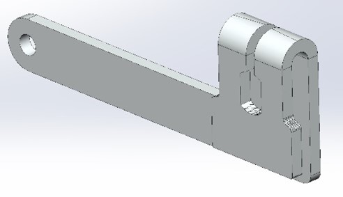
To show an element of the typical design process for Countax, take the relatively simple part as shown below, the lower link deck lift.
- This part links the deck height lever to the system so that it follows the handle as the lever moves up and down.
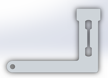
2. Defining initial geometry is completed first by drawing a basic sketch of the flat part seen below.
3. The image below shows the folded feature on CAD to allow bolts and shafts to lock and locate the part.
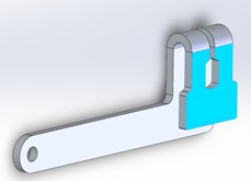
4. The part is then added to a 3D assembly drawing, constrained, and verified by conducting a motion study. This indicates if the part has been designed correctly and functions as intended whilst checking if there are any unwanted clashes within the system. The short clip below shows the lower link deck lift being modelled on CAD.
5. Once verified, the part will require a 2D detailed engineering drawing to enable it to be manufactured. The drawing will show different views of the part along with tolerance dimensions, materials, finishing and other relevant information for manufacturing purposes, which create the part specification.
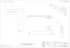
6. Knowing the part specification allows it to be laser cut from a steel sheet as a flat part first and then folded and plated. The finished part is then inspected to check it meets the specification and quality requirements.
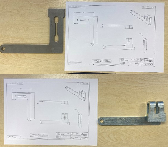
7. The part is then tested and verified on the tractor it is intended for to ensure it performs to the design intent. Once confirmed, the part can be approved and used for manufacture. Rigorous testing is done to ensure components are fit for purpose. This short clip shows the lower link deck lift tested in the machine and replicates the mechanism show in the CAD video shown earlier.
Thank you to Kevin for showcasing the various stages in the Countax design process of bringing a component from a 3D model through to it being a part signed-off for manufacture. This is just one of many involved in the design and build of a Countax tractor at our Oxfordshire factory.
If you’re interested in finding out more about Countax garden tractors, please visit your nearest Countax dealer.